
Article
How a Few Tweaks Saved a Battery Lift Point
Published
A real tearout failure on a battery enclosure lift point—the safety-factor math behind why it failed, and the material, thickness, and edge-distance fix that made it hold.
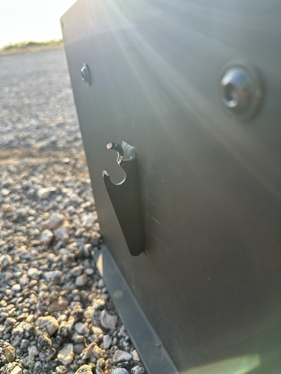
A few months ago, a client called me about a lift point that had failed in the field. The part was a sheet metal bracket welded to a battery enclosure, designed to let a crane or forklift pick up a 250 lb battery box. It had been in service for years without incident. Then, on one lift, it tore loose. They brought me in to figure out why it failed and make sure it couldn't happen again.
What follows is the actual analysis: the failure mode, the math behind it, and the redesign that fixed it. I'm sharing the real numbers because I think engineering judgment should be something you can check, not something you have to take on faith.
What Actually Failed
I knew immediately that the failure mode was tearout. Not the bolt shearing, not a broken weld, but the material between the hole and the free edge ripping out under load. It's a distinct signature once you know what to look for, and it's easy to miss if you're only checking the usual suspects like bolt shear or bearing stress.
The original part was designed by a fabricator, not an engineer, and to their credit, it held up for years before it failed. But I'd guess the design prioritized fabrication cost and speed over a real strength check. It was built from 3003 aluminum, a common choice for enclosures because it's cheap and easy to form. It's also a low-strength alloy, not the kind of material you'd choose for a load-bearing lift feature if you were starting from a strength requirement instead of a cost target. Combined with standard sheet thickness and a tight edge distance, the margin on that feature was thin from the day it was built. It just hadn't been loaded hard enough, yet, to show it.
The Analysis
I ran a tearout strength calculation on the lift point using the actual sheet thickness, hole geometry, edge distance, and the 250 lb design load, targeting a safety factor above 3.0 to account for dynamic loading during handling. A lift isn't a static load — it sees shock loading from cranes, forklifts, or uneven ground.
Nominal case — even weight distribution, static load:
That's already a thinner margin than I'd want for a lift feature, and it's the best-case loading scenario.
Worst case — uneven load distribution + dynamic shock loading:
In practice, all the weight can land on one lift point instead of two, and dynamic loading during a lift can double the effective load. Combined, that's roughly a 4x multiplier over the nominal single-point load.
A safety factor beneath 1 means the part is expected to fail under worst-case conditions. This matches what happened in the field.
The Fix
Three changes, each addressing a different part of the tearout equation:
- Switched from 3003 to 5052 — a higher-strength aluminum alloy better suited to structural and load-bearing applications
- Doubled the sheet thickness — tearout resistance scales directly with material cross-section
- Increased edge distance — more material between the hole and the free edge for the load to shear through
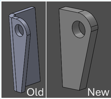
Verified safety factor came out above 4.0 under worst-case loading, well clear of marginal.
The Bigger Point
There's a real gap between "the part hasn't broken" and "it's verified to hold." That gap is where a lot of risk lives in small manufacturing. Parts get designed by whoever's available, not necessarily someone trained to catch failure modes like tearout, and they stay in production until something goes wrong. By then it's not a design review, it's an incident report.
A tearout check takes a fraction of the time a redesign after a field failure does. The cost of catching it early is a rounding error next to the cost of catching it when an incident occurs.
Most small manufacturers I talk to aren't missing engineering because they don't value it. They're missing it because hiring a full-time engineer is a big commitment for a problem that only shows up occasionally, until it doesn't, and then it's the only problem that matters. That's the gap Production Ready Engineering exists to fill: engineering judgment on the parts and problems that need it, without the overhead of a full-time hire.
If you've got a part you've been meaning to have a second set of eyes on, or you're just not sure whether something on your floor has actually been verified or just hasn't failed yet, start a DFM audit or book a free 30-minute call and let's talk.
Apply this on your floor
Want help turning insight into drawings?
We scope fast, ship shop-native packages, and keep revisions from clogging your inbox.